Define
Record program, audience plane, target level, level variation and operator roles.
TECHNOLOGY, WITH TEST CONDITIONS
Directivity, processing, amplification and control become useful only when their assumptions are visible and their results can be checked in the intended room.
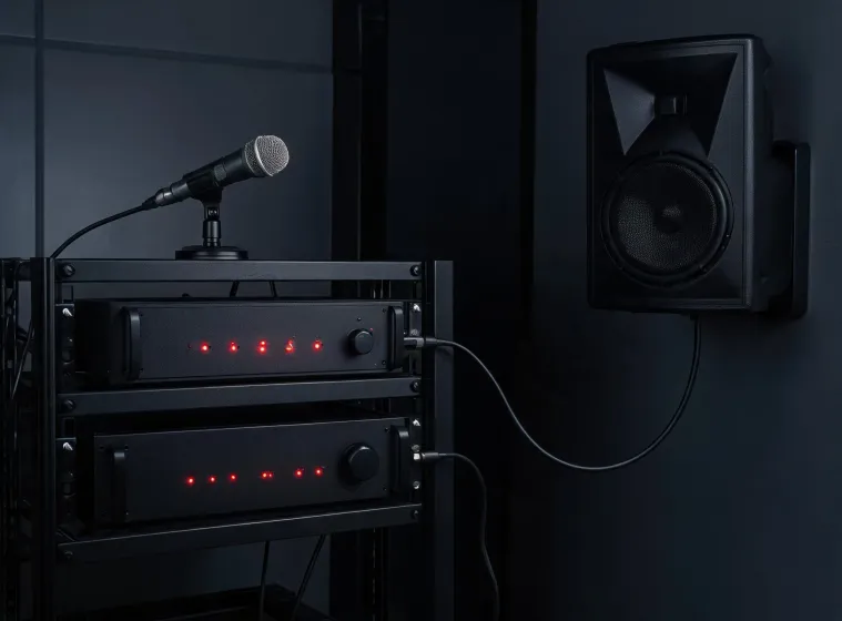
DESIGN ROADMAP
The sequence prevents a late product choice from disguising an unresolved room, network or operations question.
Record program, audience plane, target level, level variation and operator roles.
Model coverage and reflections using accurate geometry and the current loudspeaker file.
Choose analog or network transport with latency, clocking, redundancy and ownership documented.
Coordinate impedance, tap totals, crest factor, headroom, limiters and ventilation.
Verify polarity, delay, equalization and zone level under recorded test conditions.
Archive configuration, firmware, drawings and measurements for later service comparison.
TECHNICAL LENSES
Nominal beamwidth describes a region around an axis; it does not guarantee uniform level across a room. Frequency dependence, mounting, adjacent surfaces and overlap influence the result.
Equalization, crossover, delay and limiting can coordinate a known system. Presets cannot repair obstructed sightlines, severe reverberation or an incorrectly loaded amplifier channel.
Digital distribution supports flexible routing and status visibility. The benefit arrives with responsibilities for managed switches, clock election, VLAN design, multicast behavior and access security.
Use a calibrated microphone, documented interface chain and repeatable positions. Compare magnitude, phase, impulse response, polarity and level according to the commissioning question—not a single unqualified trace.
INTERFACE RESPONSIBILITIES
Room geometry, finishes, reverberation targets, sightlines and acceptable mounting locations.
Attachment loads, safety factors, circuits, grounding, heat rejection and applicable code review.
Addressing, switch configuration, clocking, multicast policy, remote access and change control.
Installation, configuration, acceptance tests, training, backup recovery and service escalation.
Compliance assets are model- and region-specific. Verify the current safety listing, EMC declaration, environmental documentation and installation instructions for the exact product before approval.
REPRODUCIBLE CHECK
Room state, microphone position, background level and occupancy condition.
Signal, bandwidth, averaging, windowing, reference distance and calibration chain.
Level, impulse, frequency and phase views tied to named measurement positions.
Saved configuration, firmware, drawings and steps another engineer can follow.
TECHNICAL REVIEW
Send a room model, intended program, signal-flow sketch and the data sheets under consideration. The review can focus on coverage, loading, transport and a reproducible acceptance path.